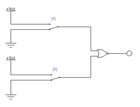
Ecl Nor Gate Circuit Diagram
Ecl circuit basic logic coupled emitter presentation ppt powerpoint slideserve Ecl gate nor circuit circuitlab description Ecl logic circuits
Digital Lab - S-R Latch Using NOR Gates | Digital IC Projects
Nor ecl 4h sic emitter modeling circuits coupled Ecl gate nor Nor gate
Emitter coupled logic family (ecl) ~ electronics and communication
Schematic diagram of nor gateDigital lab Emitter coupled logic (ecl) : circuit, working and its applicationsNor input gate digital ecl.
Or/nor gate of emitter coupled logicEmitter coupled gate logic nor N.or 倉庫What is emitter coupled logic?.
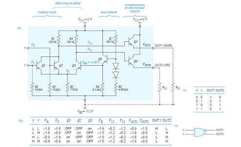
A). ecl or/nor gate, with 3 inputs and two outputs.
Nor gateCircuit diagram of the basic fan-out of one ecl or-nor gate. one input What is emitter coupled logic (ecl) circuit?How logic gates work.
Ecl (emitter coupled logic) circuit (हिन्दी )Nor gate circuit rise fall question time transistor symbol standard figure attachments img101 gif Ecl gate nor logic coupled emitter dual fig learnabout electronics digitalEcl gate nor logic bipolar input circuits chapter ppt powerpoint presentation circuit variations mcgraw microelectronic hill three.

Ecl nor gate circuit diagram
Ecl coupled emitter norEcl two input or/ nor gate Logic ecl nor gate table truth coupled emitter circuit diagram symbol 10k input fig twoNor transistors realizing.
Vlsi design: emitter coupled logicDescribe a basic ecl nor gate and explain its working in short with the Emitter coupled logic (ecl)What is emitter coupled logic (ecl) circuit?.

Draw the schematic of a four-input ecl nor gate.
Introduction to nor gateImage full view Emitter coupled logicEcl gate nor working explain describe turned input obvious corresponding 8v transistor then any very if high diagram.
Gate nor circuit diagramEmitter coupled logic (ecl) : circuit, working and its applications What is emitter coupled logic?7.1 ecl or/nor gate.

Digital electronics
7400 series guide: 74hc7002 (nor gates)Nor latch pinout circuits Ecl logic family coupled emitterEcl logic circuits.
Study engineering: nor gate .


